Intelligent Application AT the 400/120 kV Substation
of the Paks Nuclear Power Plant
János Nacsa, George
L. Kovács, Sándor Kopácsi
CIM Research Laboratory,
Computer
and Automation Research Institute, (Hungarian
Academy of Sciences)
presented in IEEE PowerTech'99
INTRODUCTION
One of the most important strategic aims of the Hungarian Power Companies
Ltd. (MVM Rt.) is to implement
an operational model of the Hungarian power system (see Fig.1.) in compliance
with the standards and practices of the European Union (EU). To fulfil
this aim, power plant modernization is the most critical and complicated
task. Within this task there is an information technology project known
as the Hungarian Electric Board's Operational-System's Technical Modernization
(ÜRIK) project. A new, computer network based communication system
was established among the power plants, the substations and the electricity
supply companies.
Many efforts have also been made locally at the various substations
to provide data acquisition and control facilities for this project. Often
the whole local operational environment had to be replaced. This was the
case at one of the most important power plants in Hungary; Paks
Nuclear Power Plant located in the middle of the country
on the river Danube. In 1998 Paks produced 38.0 percent of domestic
electrical energy production (36787 GWh). At the substation operator
level a PC-based SCADA (Supervisory Control and Data Acquisition) system
was installed. With this new information system the operators got a better
understanding of their substation and a more precise measurement of transient
events.
(Notes: English-language names of neighboring countries
are Croatia (Horvátország), Slovenia, Austria, Slovakia,
Ukraine, Romania and Serbia. Paksi E. is the Paks nuclear power
plant. In the table, transmission line lengths at each voltage level are
given.)
Figure 1. The Hungarian electricity network
The management decided that together with this reconstruction of the
operator information system, it would be valuable to establish an intelligent
advisory system to support the operators and the plant engineers with special
expert information and knowledge. Similar efforts are running in Budapest
as well [9].
The idea of applying expert systems to combine human knowledge with
computerized tools is not new in the field of electrical energy. Several
attempts were done worldwide (for
example), and in Hungary (mostly
by DYNADATA Ltd.) to use expert knowledge processing in different parts
of electrical energy systems. This paper summarizes the problems and the
results of our Paks substation project, which is different from all previous
efforts, and it presents the substation itself and the different intelligent
functions and finally implementation issues will be discussed.
The 400/120 kV Substation
Fig.2 shows the topology of the substation that has "fields" at each of
the three available voltage levels.
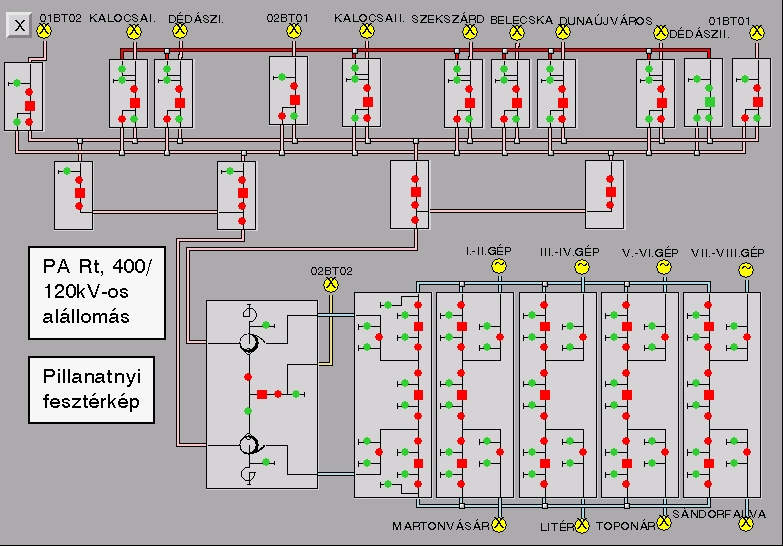
Figure 2. The topology of the 400/120 kV substation
showing "instantaneous voltages"
On the top of the figure there are 16 and 120 kV fields and on the bottom
right part are the five 400 kV fields. On the bottom left can be seen the
transformer field that contains two transformers and an 18 kV feeder. The
four, 400 kV fields at the lower right part of the figure receive power
from the generators of Paks four nuclear units. At the bottom of the figure
there are four, 400kV lines which are part of the Hungarian backbone electricity
net. The 120 kV fields supply power to cities nearby and can also feed
power back to the nuclear units when it is necessary to restart a unit
after a shutdown.
The basic switching elements of the substation are the circuit breakers
(squares on the figure) and the line and ground disconnectors (circles).
The circuit breakers can switch high currents, while the disconnectors
are used to isolate portions of the substations from high voltage or securely
connect parts of the substations to ground. The operator remotely switches
most of these elements but in case of short circuits or other disturbances,
protective relays automatically open or close the circuit breakers to keep
other equipment safe.
INTELLIGENT FUNCTIONS
The requirement specification of the project identified the following needs
and problems in the substation from the management and organizational point
of view:
-
The management wanted an intelligent advisory system to support the operators
with the know-how of the engineers, especially in alarm situations.
-
To reduce maintenance costs and to assist maintenance design it is valuable
to collect the switching information and operational history of all types
of equipment (how many times did a circuit breaker switch, and why, when
and how did it switch).
-
The management wanted a better understanding of the technology to compare
theoretical protection sequences with the actual performances of the equipment.
-
Plant engineers need effective assistance in better understanding some
error/disturbance events in the substation and they need support in recovery
and some other design tasks (as for example switching sequence design).
To fulfill the requirements, a multifunctional system was designed to be
deeply integrated into the SCADA system and its environment. One complex
system had to be developed where the various SCADA and intelligent functions
could share data. The implementations of the functions were different,
with rule- and procedure-based technologies mixed according to the types
of functions and their timing requirements.
Two types of users were defined. The first is the operator of the substation,
who gets simple warnings if any of the functions detect a problem; and
the second is the electrical engineer (plant engineer) who can get various
statistics about the substation and can use the data as needed, e.g. to
plan future maintenance.
Finally the following intelligent functions were defined and implemented
in frames of the project:
A. Topology analysis with voltage and current map generation,
and determination of dangerous topologies
The SCADA system provides measurements of many voltage and current
values at various points of the substation. The number of these values
allows generating an actual voltage and current map for the operator. This
calculation is done periodically and the system also determines whether
any parts of the substation are close to a dangerous state or not. Often,
the present topology and some secondary signals together can indicate an
alarm situation that is very difficult for a human operator to recognize
(e.g. oil pressure unstability when only one transformer is on).
B. Equipment diagnostics and maintenance design based on the switching
types of the different items of switchgear (closed, open, trip)
Before the new SCADA system was implemented only the catalog data were
available; there was no information on actual performance. This function
monitors the switching actions of all equipment and calculates various
features, e.g. the slowest and the quickest switching time, deviation,
average etc. It compares this information with the catalog data and if
necessary warns the operator. It also examines the conditions of the switches
and classifies them according to the performance of each. The result of
the classification is compared with the catalog data to provide maintenance
data about the aging of the equipment. At Paks this is very important information
because maintenance of substation equipment must be scheduled in coordination
with maintenance outages of the nuclear units.
C. Intelligent interlocking system based on the measured voltages
and currents
Based on the topology it is possible to determine for each item of
equipment whether it is permissible to switch it or not. This function
sends updated information to the operator and sends warning messages if
conflicts are detected between the topology and the built-in interlocking
mechanism. This mechanism works with logical equations.
D. Diagnostics of disturbances, determination of the places and
types of short-circuits, and advising in recovery procedures
When an error/disturbance situation occurs the SCADA system sends many
error and warning signals to the operator, and it is very difficult for
the operator to quickly determine the real reason of those signals. Typically
many changes occur within an interval of 10-100 ms. The advisory system
detects the changes in proper order, and tries to fit the predefined "protection
samples" with a kind of tolerance and finally informs the operator about
the best fitting sample. Earlier this information was available only several
hours or even days later, when the engineering team analyzed recordings
made by the (analog) measurement equipment.
The table below (Table 1.) gives a part of one of these protection
samples.
| Sample name |
Field
range |
Serial
Num. |
Signal |
Sign
type
|
Sign
value
|
Last
sign
|
Time
rel.
|
Time
tol+
|
Time
tol-
|
Importance
|
Maint.
|
| 910%_TVFSZFNVS |
2,3,5 |
1 |
910%_KT |
M
|
D
|
8
|
80
|
20
|
10
|
F
|
IF
|
| 910%_TVFSZFNVS |
2,3,5 |
2 |
910%_ÖT |
M
|
D
|
8
|
80
|
20
|
10
|
F
|
IF
|
| 910%_TVFSZFNVS |
2,3,5 |
3 |
910%_KT |
M
|
B
|
16
|
100
|
20
|
20
|
F
|
|
| 910%_TVFSZFNVS |
2,3,5 |
4 |
910%_ÖT |
M
|
B
|
16
|
100
|
20
|
20
|
F
|
|
| 910%_TVFSZFNVS |
2,3,5 |
5 |
910%_KT |
M
|
K
|
18
|
80
|
20
|
10
|
F
|
IF
|
| 910%_TVFSZFNVS |
2,3,5 |
6 |
910%_ÖT |
M
|
K
|
18
|
80
|
20
|
10
|
F
|
IF
|
| 910%_TVFSZFNVS |
2,3,5 |
7 |
910%_TV1$E |
$
|
F
|
|
|
|
|
F
|
|
| 910%_TVFSZFNVS |
2,3,5 |
8 |
910%_TVA1O |
V
|
F
|
0
|
44
|
5
|
5
|
F
|
|
| 910%_TVFSZFNVS |
2,3,5 |
9 |
910%_KT$AVO1 |
$V
|
F
|
0
|
44
|
5
|
5
|
F
|
|
| 910%_TVFSZFNVS |
2,3,5 |
10 |
910%_ÖT$AVO1 |
$V
|
F
|
0
|
44
|
5
|
5
|
F
|
|
| 910%_TVFSZFNVS |
2,3,5 |
11 |
910%_TV2$E |
$
|
F
|
|
|
|
|
F
|
|
| 910%_TVFSZFNVS |
2,3,5 |
12 |
910%_TVA2O |
V
|
F
|
0
|
58
|
20
|
20
|
F
|
|
| 910%_TVFSZFNVS |
2,3,5 |
13 |
910%_KT$AVO2 |
$V
|
F
|
0
|
60
|
20
|
20
|
F
|
|
| 910%_TVFSZFNVS |
2,3,5 |
14 |
910%_ÖT$AVO2 |
$V
|
F
|
0
|
60
|
20
|
20
|
F
|
|
| 910%_TVFSZFNVS |
2,3,5 |
15 |
910%_TV2FZI |
J
|
F
|
|
|
|
|
K
|
|
| 910%_TVFSZFNVS |
2,3,5 |
16 |
910%_VA |
A
|
F
|
20
|
2000
|
200
|
200
|
K
|
|
| 910%_TVFSZFNVS |
2,3,5 |
17 |
910%_SY1V |
J
|
F
|
0
|
64
|
10
|
10
|
K
|
|
| 910%_TVFSZFNVS |
2,3,5 |
18 |
910%_TVA1O |
V
|
F
|
16
|
44
|
5
|
5
|
F
|
|
| 910%_TVFSZFNVS |
2,3,5 |
19 |
910%_TVA2O |
V
|
F
|
16
|
58
|
20
|
20
|
F
|
|
| 910%_TVFSZFNVS |
2,3,5 |
20 |
910%_TV2$E |
$
|
M
|
1
|
40
|
30
|
20
|
N
|
|
Table 1. Predefined protection samples
In the knowledge acquisition phase of the project about 200 different
disturbance events were collected (presently only in the 400 kV part of
the substation). The table shows a protection sample defined by the technology
expert of the substation. It is a meta sample which means that it defines
3 X 3 different samples (3 fields - 400/2, 400/3, 400/5 and the 3 phases
- R, S, T). This table describes the logical connections among the signals,
the importance of them, and the format of the signals (e.g. 0->1->0). For
each sample there are "forbidden" signals defined, which means that if
such a signal exists among the collected data then that sample must not
fit.
The fitting algorithm first selects those samples for which all "key"
signals exist and no "forbidden" signal is present among the collected
data. It then classifies the samples as to how well they fit with the other
(important, non-important and extra) signals. In the next step the refinement
is done, comparing the timing context of the samples and the elements of
the collected data set.
Fig. 3. shows the representation of the protection sample given above
in G2 as a graph where the relationship among the signals can be seen as
well. It is an unsuccessful attempt to reclose a circuit breaker after
a short circuit near the other end of a 400kV-transmission line.
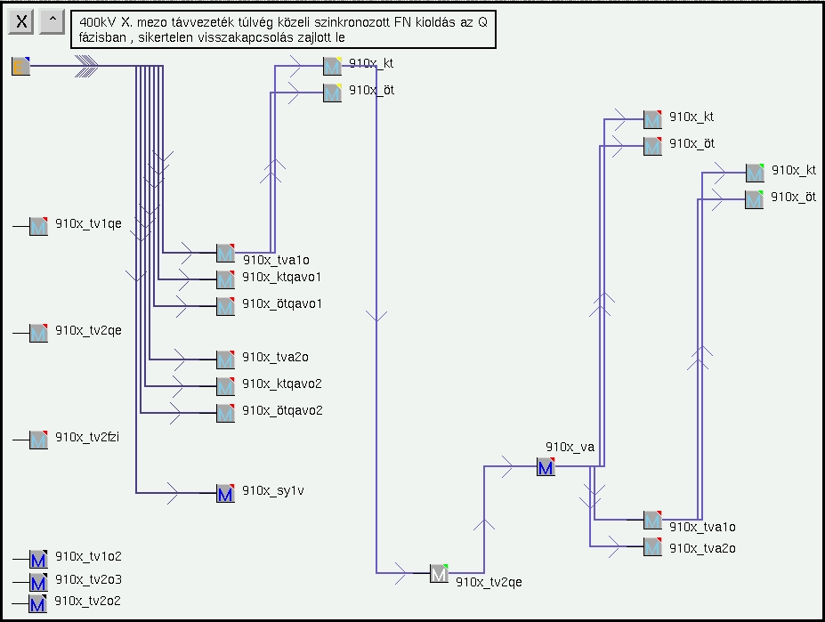
Figure 3. Representation of a protection sample
in the G2 system
["400 kV line, in the X field, was deenergized
to clear a short-circuit fault attempted reclosure was not successful."]
In the realization of this function procedural and rule based methods
were mixed. The trigger of the function and most of the data processing
is coded in procedures but a set of rules should fire to determine which
is the most fitted sample.
Each protection sample includes the information about the current peak
load (e.g. full, half, quarter or normal) of every circuit breaker that
plays a role in the sample. The best-fitted sample defines the maintenance
message that is sent to the maintenance design staff.
E. Automatic generation of switching sequences
The operator should plan the switching sequence of the equipment when
such a command comes from the nuclear plant operators or from the control
center of the Hungarian Electric Board. The user interface of the command
selection function was designed for operators unskilled in computer science.
The starting state of the function is the present state of the substation.
The final state is automatically calculated from the command and the present
state. The switching sequence should be automatically generated using basic
electrical rules and the special custom rules followed at Paks. The generated
sequence is printed for the operator, who has to check and sign it, then
execute it manually. Fig. 4. gives a list of these commands and some examples.
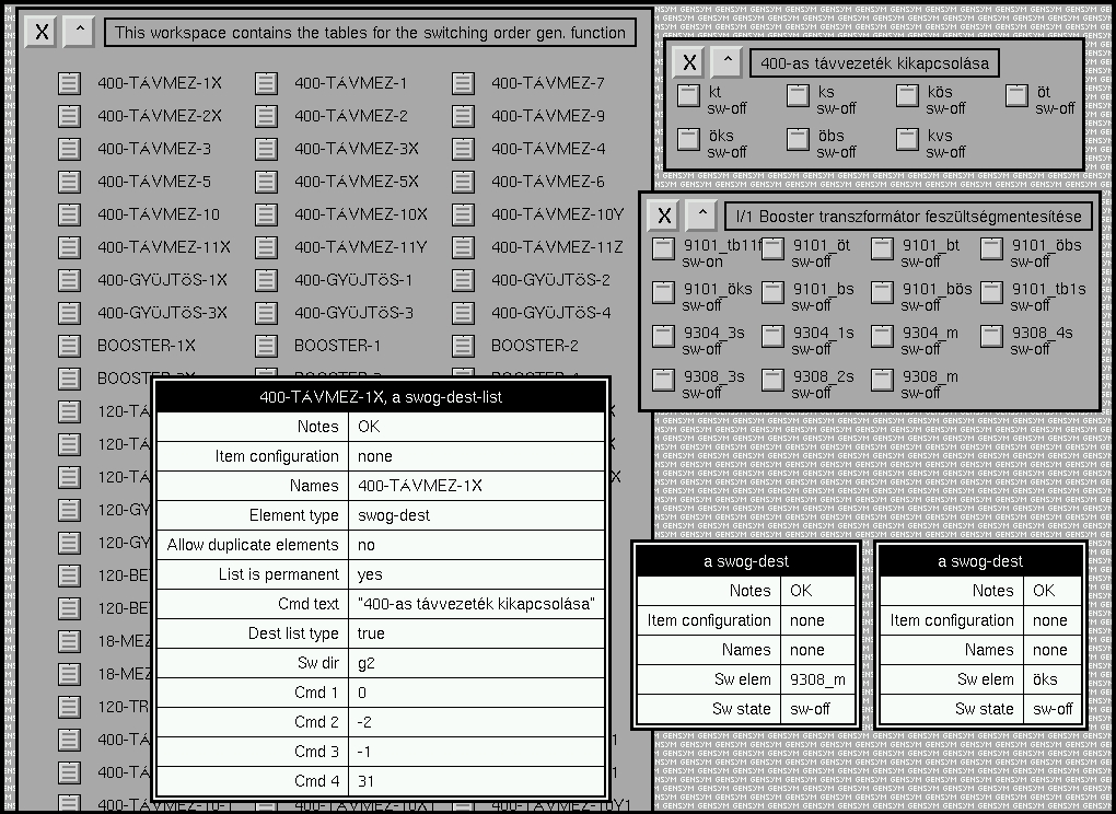
(Note: The titles of the workspaces (windows) on
the right are"400 kV line switch off" and "I/1 Booster Transformer removed
from voltage".)
Figure 4. A list of some switching sequence generation
commands and some examples
The algorithm defines step by step the sequence of elements to be switched.
It uses the SCADA systems built in interlocking equations and invokes
the rules of the experts. The knowledge acquisition process by which the
rules given by the experts are represented is done very easily in the G2
[3] code. In the following lines these rules are illustrated-one electrical
and two custom rules in switching-off commands:
-
for any disconnector D in SWG-LIST if there exists a circuit-breaker
in SWG-LIST then remove D from SWG-LIST
-
for any 400-line-disconnector LD1 in SWG-LIST if there exists a 400-line-disconnector
LD2 in SWG-LIST such that ( the branch of LD2 = the symbol br-ö) and
LD1 is not the same object as LD2 then remove LD1 from SWG-LIST
-
if there exists a sf6-line-disconnector LD1 in SWG-LIST such that (
is-contained-in-text ("_BS" , the text of the names of LD1 ) = true ) and
there exists a sf6-line-disconnector LD2 in SWG-LIST such that ( is-contained-in-text
("_BÖS" , the text of the names of LD2 ) = true ) then remove LD2
from SWG-LIST and conclude that SWG-NXT = the names of LD2
HARDWARE-SOFTWARE ENVIRONMENT
To realize this complex system, the G2
Intelligent Real-Time System was chosen because of the following reasons:
-
Its capability of handling very different type of data and information
processing methods
-
Real-time and object oriented features
-
Good, easy to use graphical development tools
-
Easy to understand and easy to use, English-like programming language
-
Support of cyclic development (e.g. rapid prototypes)
-
Relatively easy interfacing to different external systems (e.g. SCADA,
SQL)
-
More than 6000 industrial references all over the world including power
plant sites ([5],[6],[7],[8])
-
5 years experience in design and programming of G2 at SzTAKI
The hardware-software environment of the whole system is the following:
-
Server: MS WinNT Server to run FIX SCADA, MS SQL, G2
-
Operator Station: MS WinNT WS to run the FIX SCADA Display. The G2 messages
and displays are included in the operators SCADA station.
-
Engineer Station: MS Win NT/95/98, Gensyms Telewindows
SOME SOFTWARE IMPLEMENTATION ISSUES
As a FIX-based (Intellution) SCADA
system was implemented at the substation [2] we had to be connected to
the information sources of it, as the SCADA system is connected to all
external data of the system. This way an intensive use of GSI was necessary
to get and send SQL data and FIX specific ODB and EDA data, etc. Moreover
for certain functions individual C language I/O programs had to be written
and integrated to the whole system. As the requirements of the SCADA system
were fixed before we started the G2 development we had to keep ourselves
to the SCADA screen designs in general and with all elements of G2 on the
screens, too. Thus a completely SCADA-like set of G2 windows serves the
plant engineer to evaluate and analyze past events, and to prepare decisions
for the future, and a restricted number of SCADA-like G2 windows assist
the operator for decision making.
CONLUSIONS
An intelligent, multi-function advisory system was implemented and introduced
which supports the operators and plant engineers in the 400/120 kV substation
of the Paks Nuclear Power Plant. The different but closely coupled functions
were briefly explained.
Functions based on our experience at Paks could be used in other (similar)
substations, as well. The hardware-software environment (G2-SCADA-SQL architecture)
is the same as in the plant computers at Paks, so that many future applications
where intelligent information processing is needed could be developed using
the experiences of this project.
This project is also the first industrial application of G2 in Hungary.
ACKNOWLEDGEMENT
The project was sponsored and assisted by
the Paks Nuclear Power Plant Ltd. The contributions of Eurocom Ltd., as
system integrator of the SCADA system, Eroterv Ltd. as domain expert are
accepted and highly appreciated.